Chapter 13 of The Water Works of the City of Philadelphia: The Story of their Development and Engineering Specifications
Compiled in 1931 by Walter A. Graf (Staff Engineer, The Budd Company, Philadelphia), with the assistance of Sidney H. Vought and Clarence E. Robson. This online version was created from an original volume at the Historical Society of Pennsylvania, Catalog No. WZ 23591 (4th Fl. Folio).
Walter Graf History Home Page
(With Notes on the Text, Preface, and Acknowledgements)
Reading the Preface will give a quick overview of the beginnings and expansion of the Philadelphia water system.
To see a collection of plans and technical drawings of the Frankford Pumping Station and its associated pipeline, pumping engines, and reservoir, click here.
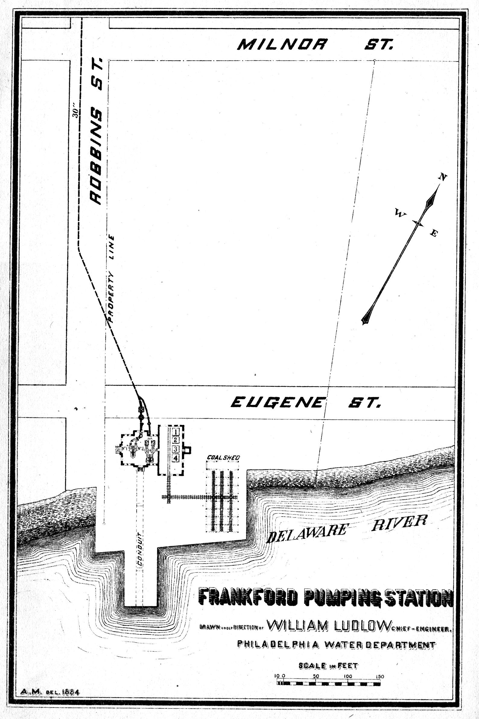
ACTIVE PROMOTION FOR THE building of a pumping station at Frankford was started in 1872 with the passing of a loan by Councils. In 1873 it was suggested by Dr. Wm. H. McFadden, then chief engineer of the Water Bureau, that the pumping station for these works be located at Dark Run Lane and the Delaware River, and that the necessary reservoir be located in the vicinity of what was then known as the Oxford and Kensington Turnpikes. The site finally selected for the pumping station was at Robbins Street and the river and that for the reservoir at Second and Comly Streets, a site then known as the Wentz Farm. The surveys for these works were completed in 1874, and construction work was started on the pumping station in the early spring of 1875, and on the reservoir on October 28, 1875.
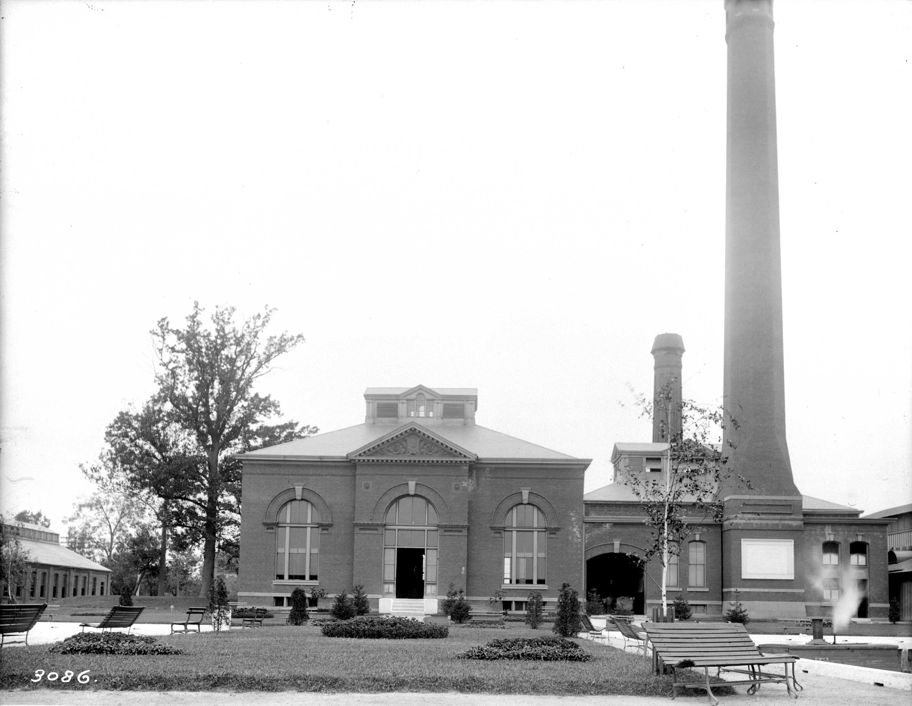
At first it was intended to build a reservoir of 11 million gallons capacity, but this was later changed to approximately 36 million gallons, at 167 feet city datum. The pumping station was built to accommodate two 10 million gallon pumping engines, and the first of them was contracted for in 1875. The station house was built by Prior and West, Contractors of Trenton, New Jersey, to whom the contract was awarded on June 13, 1876. A station wharf, and a water intake and foundations, were built by a Mr. R. A. Malone under a contract awarded on April 25, 1876. The inlet conduit ran well into the river and was provided with a top that could be used as a wharf, providing 13,000 square feet of wharf area. Coal bunkers with a storage capacity of 1,500 tons were also constructed.
The reservoir on the Wentz Farm was completed in July 1877, and the station started pumping December 1, 1877. It was found that the forebay was soon pumped dry. Investigation disclosed the fact that some malicious person had placed bulkheads in front of the wooden inlet conduit to prevent the free inflow of water into the forebay. This was quickly remedied and pumping resumed. On December 10, 1877, water was delivered into the reservoir, and supplied to the residents of Frankford. The pumping main between the station and the reservoir was 30 inches in diameter and 20,250 feet long. A rubber-coated pipe one inch in diameter was laid alongside the pumping main so that the height of the water in the reservoir could be indicated at the engine house.
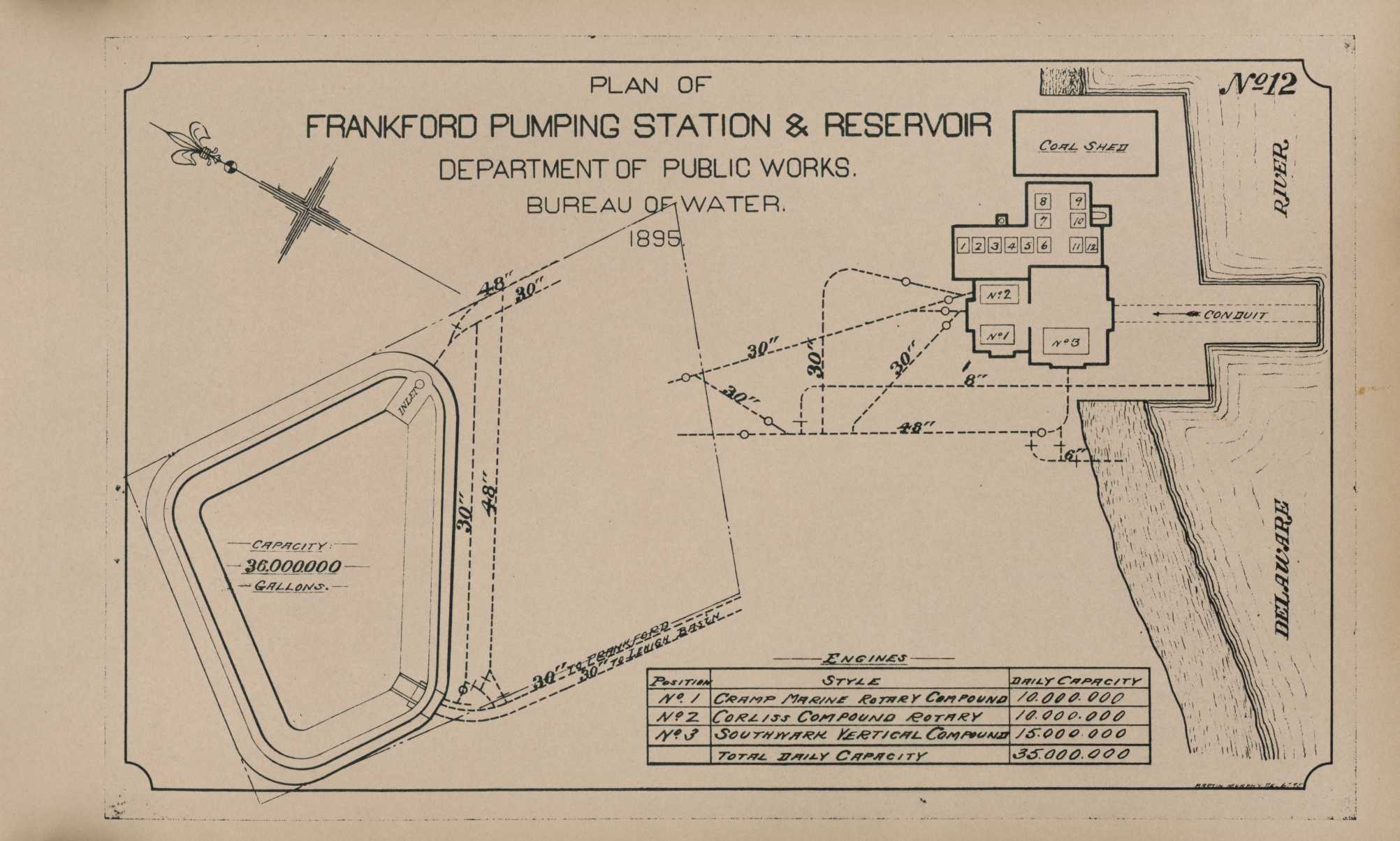
The first engine, No. 1, was built by the Wm. Cramp and Sons Engine Company. It was a marine compound rotary type of 10 million gallons daily capacity. It had one high pressure cylinder of 40 inches bore and a 60-inch stroke, and one low pressure cylinder of 69 inches bore and 60-inch stroke. Connected to the engine were two double acting plunger pumps, each of 21-inch bore and 60-inch stroke, and capable of a total water lift of 187.5 feet.
After having been in operation approximately seven months, on July 15, 1878 the engine pump cylinders broke. Then the small 2 million gallon Worthington engine was rushed from the Fairmount station and erected in this station where it became known as engine No. 2. This No. 2 engine was the one erected at the Fairmount pumping station in 1869 to supplement the water power driven pumps which were then seriously handicapped by the extremely low water in the Schuylkill River occasioned by the severe drought. No. 2 engine furnished all the water for this district until May 3, 1879, when the repairs to engine No. 1 were complete and it was again in operation.
A duplicate of engine No. 1 was urgently requested in 1880 as a reserve against accident to the equipment in service. A new 10 million gallon Corliss compound rotary engine was provided and began service August 5, 1884. The Worthington engine was removed from the engine house in order to make space for the new Corliss. The Corliss was built and erected by Robert Wetherill Company of Chester, Pa. It had a high pressure cylinder of 28 inch bore and 36 inch stroke, and a low pressure cylinder of 56 inch bore and 36 inch stroke, with two double plunger pumps of 20 inch bore and 36 inches stroke. Its total water lift was 187.5 feet. This engine was soon found to be too light in construction for its duty, and it was suggested that it be transferred to some other station where the lift requirements were lighter, and that it be replaced by a heavier engine.
In 1893, a new 15 million gallon pumping engine was completed and installed on contract by the Southwark Foundry and Machine Company of Philadelphia. A year later, additional boilers, a smoke stack and an addition to the station were included.
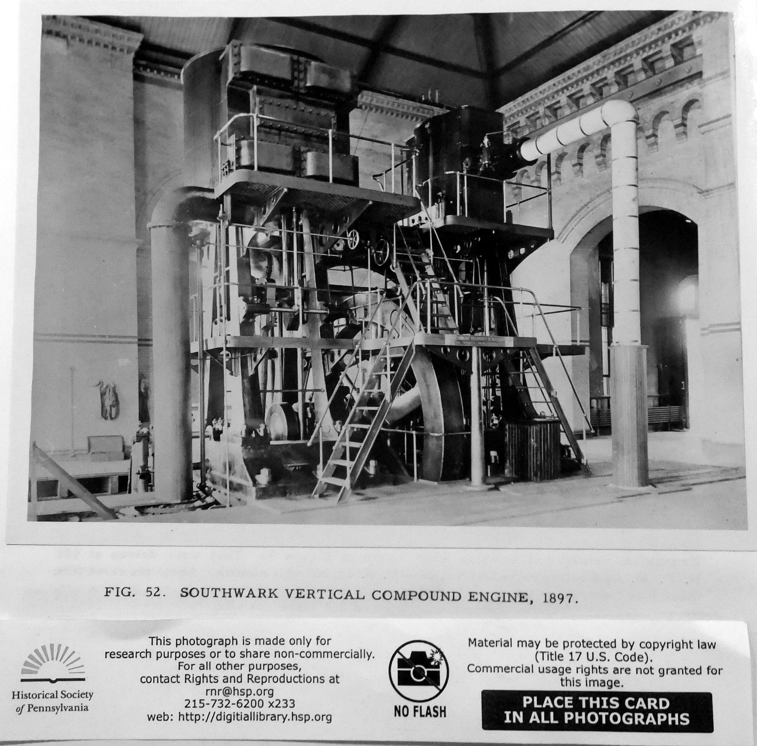
This new engine (See FIGURE 52), which then became No. 3, was a vertical compound flywheel type, and although rated at 15 million gallons per day was expected to be capable of delivering 20 to 25 million gallons. The engine was completed in 1894, but it was not accepted by the Bureau until June 1897 because of a series of defects which resulted in a broken piston and necessitated its remaining in the hands of the builders until the defects were remedied. During the time between August 1, 1894 and December 31, 1896, the builders experimented with a hydraulic attachment for operating the pump valves.
In 1895, and again in 1898, additional reservoir storage facilities were again recommended, for the demands of the districts supplied by this station had reached such proportions that a sedimentation period of only 1½ days was possible with the existing reservoir, and this was entirely inadequate for the type of water delivered to this basin.
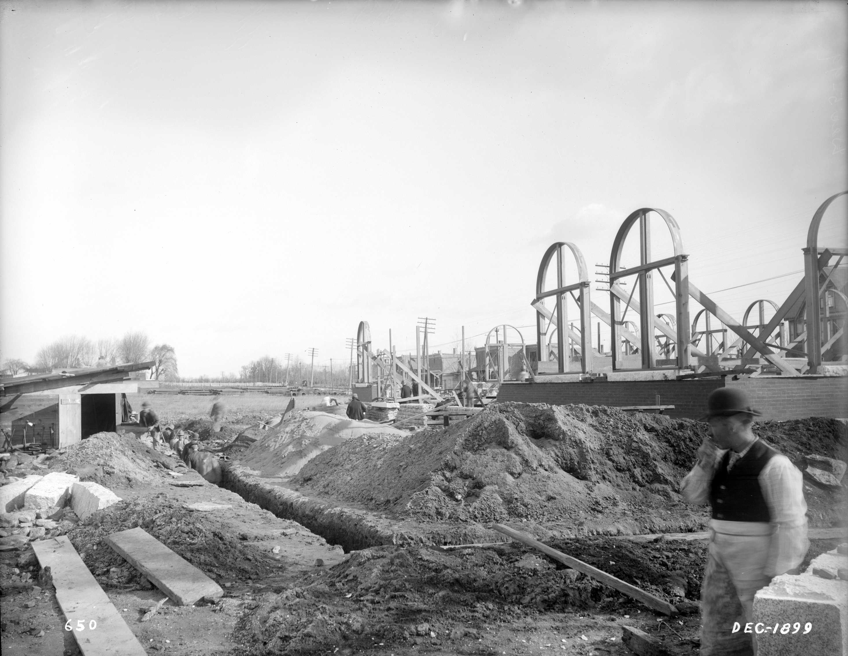
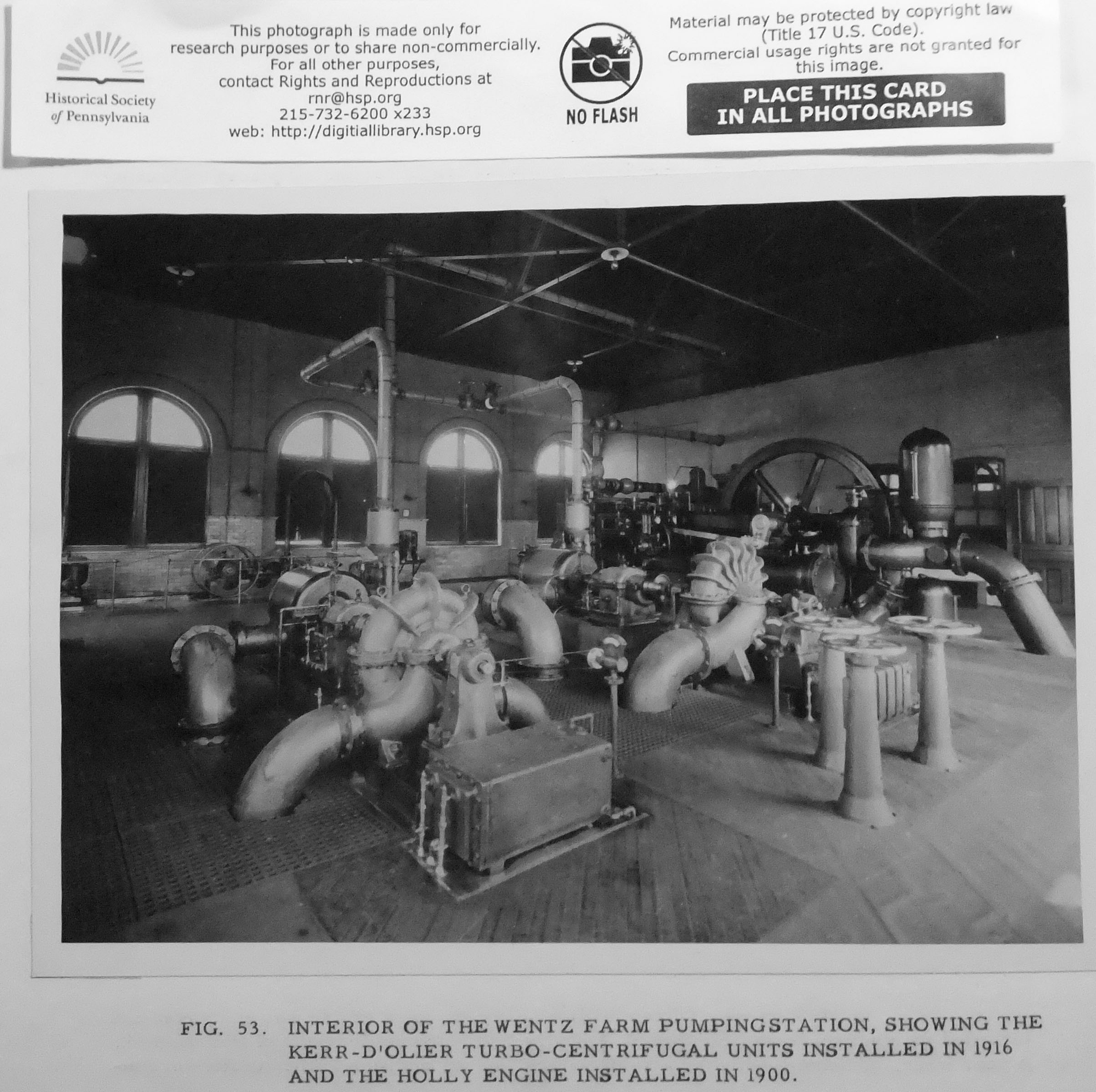
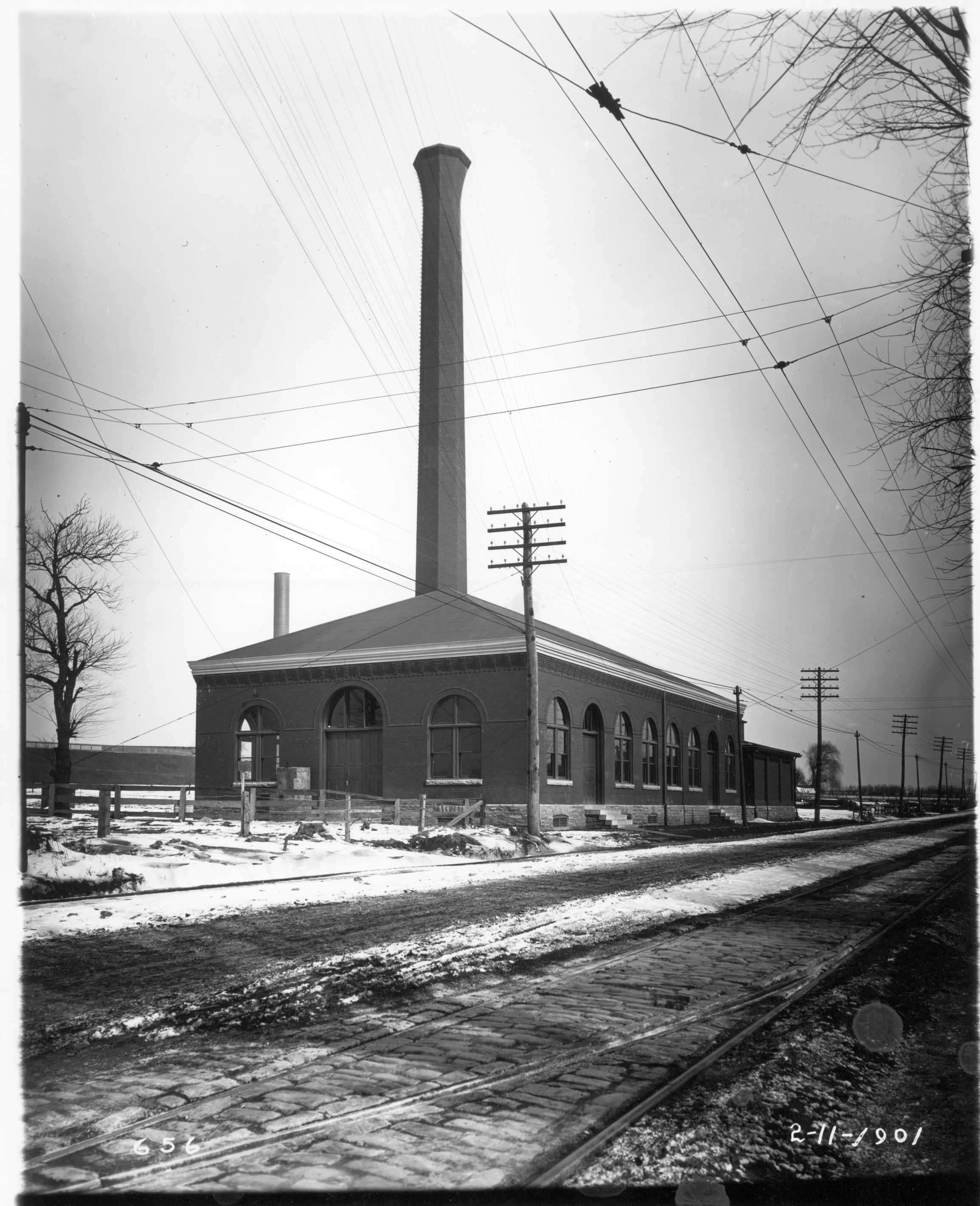
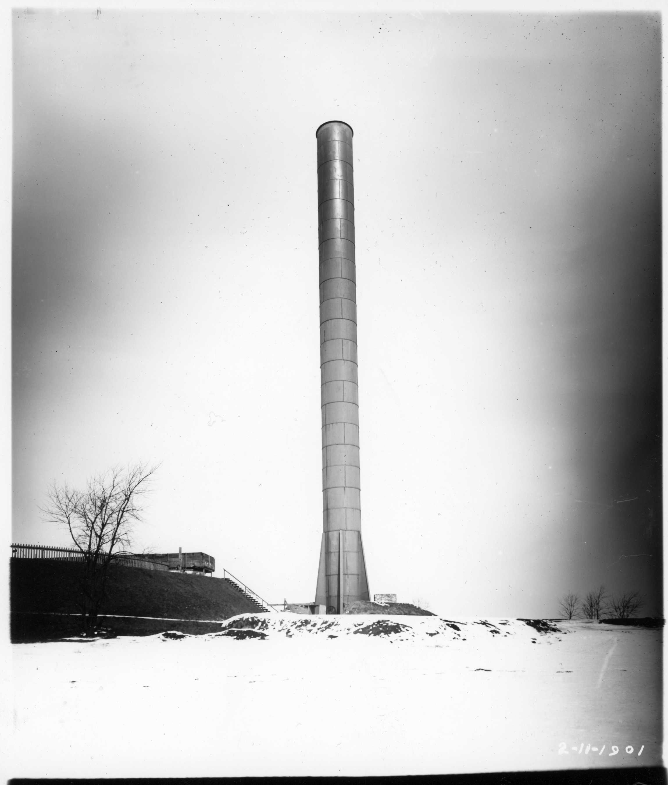
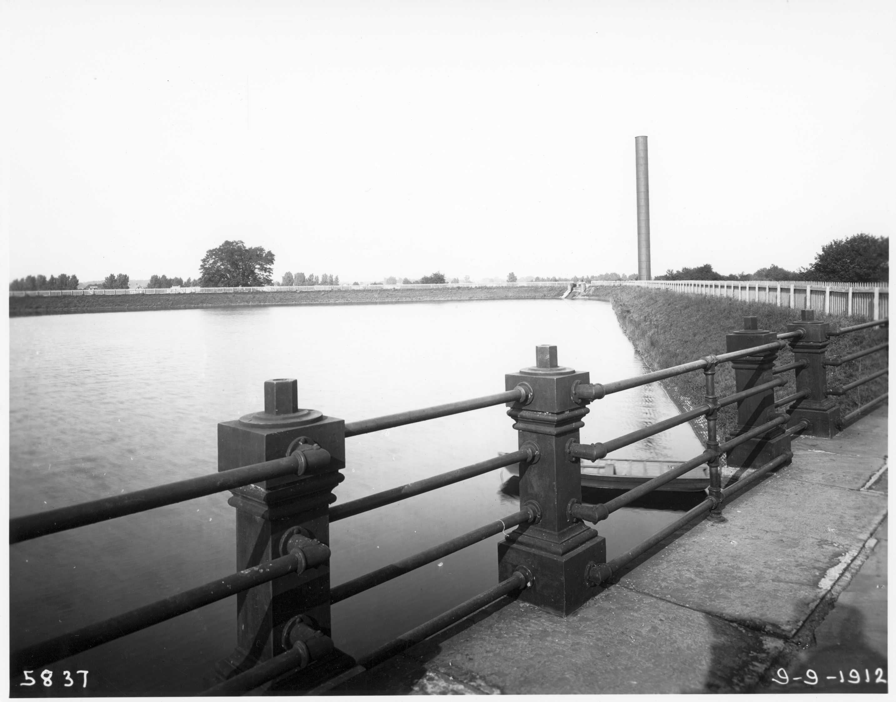
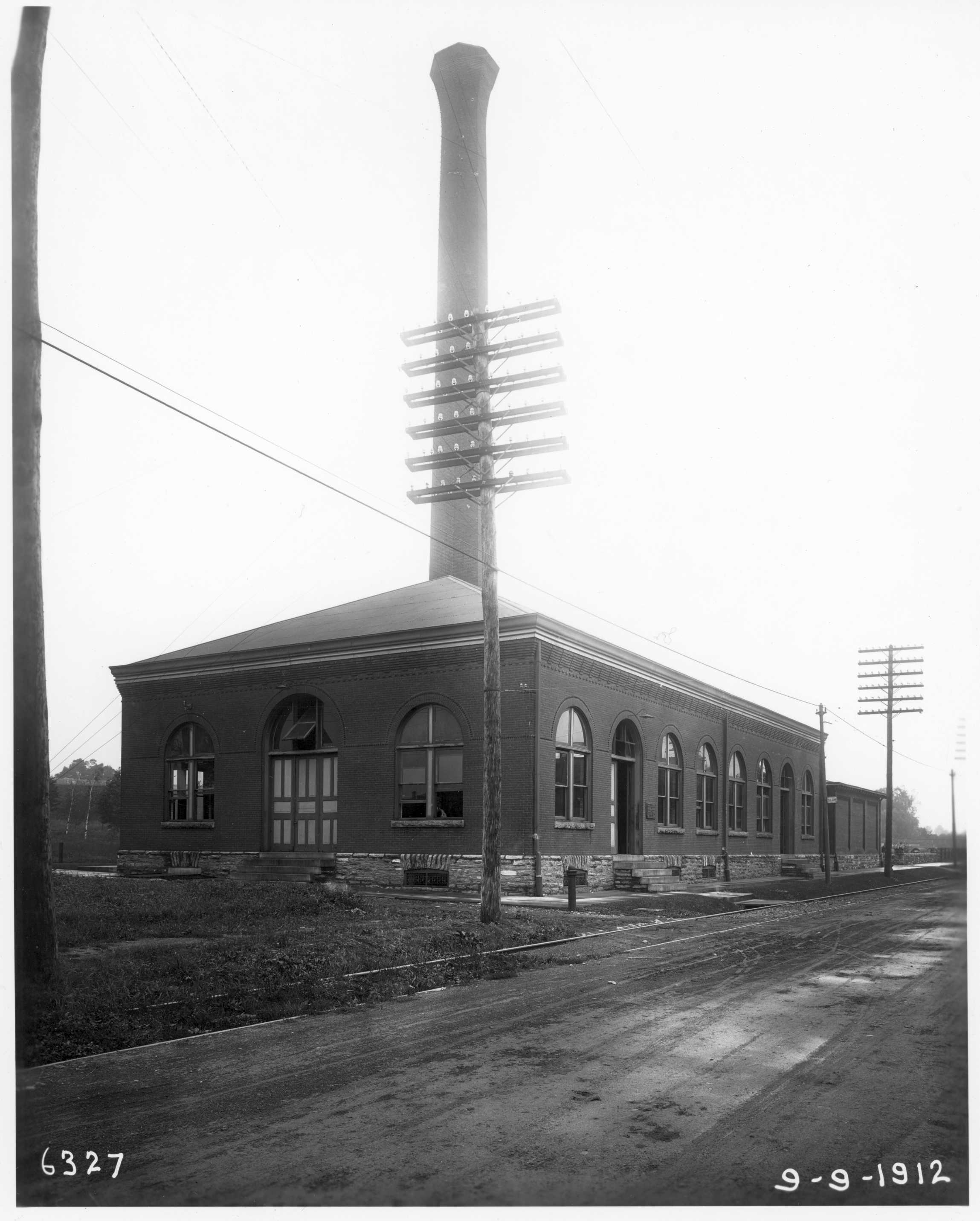
Since the reservoir on the Wentz Farm was in the midst of several thriving suburbs it was later deemed advisable to provide these districts with the water stored in their vicinity. In line with this reasoning, on August 22, 1899, a contract was awarded for the erection of a 3 million gallon pumping engine, together with a boiler house, three boilers, a stack, and a standpipe for a new pumping station to supply the Fox Chase, Lawndale and other districts in this vicinity. This new station was known as the Wentz Farm (or Frankford) high service pumping station. It was completed and placed in service in the fall of 1900. This station was located close to the Wentz Farm reservoir. Water from the reservoir was conveyed through a 20-inch main to the high service engine house, and there pumped to points of delivery under a head of 166 feet through 7,980 feet of 20-inch diameter mains, and 5,071 feet of 16‑inch diameter mains. The standpipe was located at the northeast corner of the reservoir. It was 11 feet in diameter, 150 feet high, and provided with a 12‑inch diameter overflow pipe discharging into the reservoir. The 3 million gallon pumping engine was manufactured by the Holly Manufacturing Company of Lockport, New York, and began service October 13, 1900. This engine was a horizontal, rotative, high duty, compound condensing type, with superimposed high and low pressure cylinders, the high pressure of 12‑inch diameter, and the low pressure of 32‑inch diameter while the plungers of the double acting pump were 137/8 inches in diameter and operated through a stroke of 24 inches at 35 R.P.M. It appears in the background of FIGURE 53.
The D’Auria 2.5 million gallon duplex engine, which was first installed at the Roxborough pumping station in 1899, was moved in 1901 to the Wentz Farm (or Frankford) high service station. There it entered service on a revised rating of 4 million gallons per day on account of the lower lift required at this station.
November 25, 1901, a 10 million gallon Southwark vertical compound flywheel type engine, which had first been installed at the Roxborough works, was placed in operation at the Frankford pumping station, and was designated No. 4 engine. During the same year (1901) plans and specifications were prepared for a reconstruction of the Wentz Farm reservoir to increase its capacity. It was a part of this plan to have this reservoir work in conjunction with the Oak Lane reservoir, as a compensating and distributing reservoir for filtered water from the new Torresdale filters.
The original Frankford pumping station continued to function satisfactorily and to adequately serve the steadily increasing demands of the districts which it supplied until 1905. In this year the three new 20 million gallon pumps at the Lardner’s Point pumping station (originally Frankford Station No. 2; see next chapter) took over the regular service of these districts. The old Frankford station ceased regular pumping in April 1905; but during 1906 and 1907 it was kept under steam and did a small amount of pumping. In 1908 not a gallon of water was pumped, although the station was kept under steam during the entire year. While the old station seemed superfluous, this arrangement continued until 1914, when the station’s activities ceased entirely, for it had been completely supplanted by Lardner’s Point, A few years later the old equipment was disposed of and the station entirely demolished.
The Wentz Farm high service station survived the parent Frankford Station. Early in 1914 the districts of Somerton and Byberry were added to the duty of the Wentz Farm station and an appropriation was made and a contract let for additional pumping equipment. This new equipment, which did not see service until 1916, consisted of one 2.5 million and one 5 million gallon Kerr-D’Oiler turbo-centrifugal pumps. These are pictured as installed in the foreground of FIGURE 53. After another five years plans were developed for transferring the service handled by the Wentz Farm high service station to the Lardner’s Point pumping station, to thereby eliminate the high overhead expense of operating the isolated Wentz Farm station. In 1921 the Wentz Farm reservoir was abandoned, and the basin was drained. The territory northerly and westerly from Frankford, which formerly received its supply from this reservoir, was transferred to the Oak Lane Service. In 1924, the Lardner’s Point pumping station assumed the pumping burden formerly carried by the Wentz Farm station, and it was formally abandoned. The empty engine and boiler house and the stack of the station and small portions of the reservoir embankment still mark the site.