Chapter 1 of The Water Works of the City of Philadelphia: The Story of their Development and Engineering Specifications
Compiled in 1931 by Walter A. Graf (Staff Engineer, The Budd Company, Philadelphia), with the assistance of Sidney H. Vought and Clarence E. Robson. This online version was created from an original volume at the Historical Society of Pennsylvania, Catalog No. WZ 23591 (4th Fl. Folio).
Walter Graf History Home Page
(With Notes on the Text, Preface, and Acknowledgements)
Reading the Preface will give a quick overview of the beginnings and expansion of the Philadelphia water system.
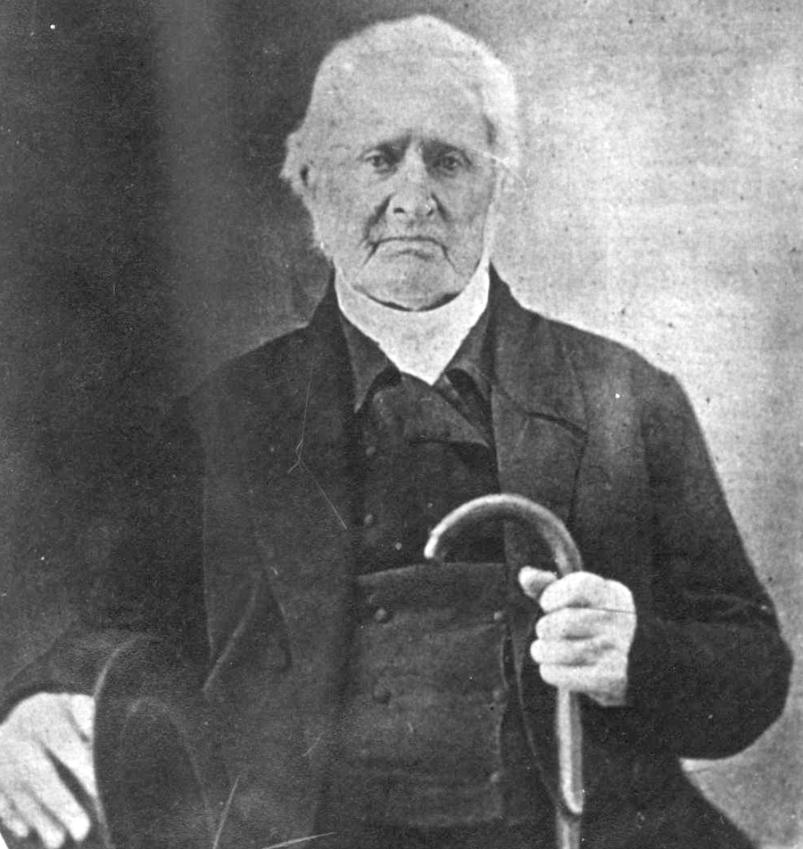
WITH THE APPROVAL of Councils and encouraged by the enthusiasm of the citizenry of Philadelphia, Benjamin Henry Latrobe applied himself to the stupendous task of designing and constructing the first Philadelphia Water Works. After the sites and general design had been decided upon, his first move was to select a reliable and trustworthy assistant. His choice fell upon Frederick Graff, who was following his chosen vocation as a draftsman when Latrobe made his acquaintance and was evidently attracted by the young man’s ability. Frederick Graff was a native of Philadelphia, born August 27, 1776, in the house on Market Street near Seventh, wherein, according to historians, Thomas Jefferson drafted the Declaration of Independence. Jacob Graff, Jr., Frederick’s father, was a successful builder. His grandfather, Jacob Graff, Sr., came to America from Hildesheim, Germany, in 1741, and established himself in the brick business which grew large and prosperous.
Actual work on the water works was begun in 1799 according to plans designed by Latrobe and described by Frederick Graff in one of his annual reports to the Watering Committee:
“A Basin was formed on the Schuylkill River at the foot of Chestnut Street extending from low water mark, 200 feet eastwardly, and 84 feet wide, provided with a set of tide lock gates. The bottom of this basin was three feet below low water mark; from this the water flowed through a sluice to a second basin or rather an open canal, 40 feet wide, and 160 feet long; the sides of both these basins were inclined, paved and coped with marble; at the head of the canal was a sluice gate set in marble, which admitted the water into a subterraneous tunnel of oval form, six feet in its greater diameter, and 300 feet long, cut nearly its whole distance through solid rock, with its bottom placed level with low water, and emptying into a well in which was placed the pump of the lower or Schuylkill engine. This shaft or well was 39 feet deep and 10 feet in diameter, in it was placed the pump, the bottom chamber being on a level with low water, by which the water was raised into a brick tunnel six feet in diameter and 3,144 feet in length, which passed up Chestnut Street to Broad and then north on Broad Street to the Centre Square Station House.”
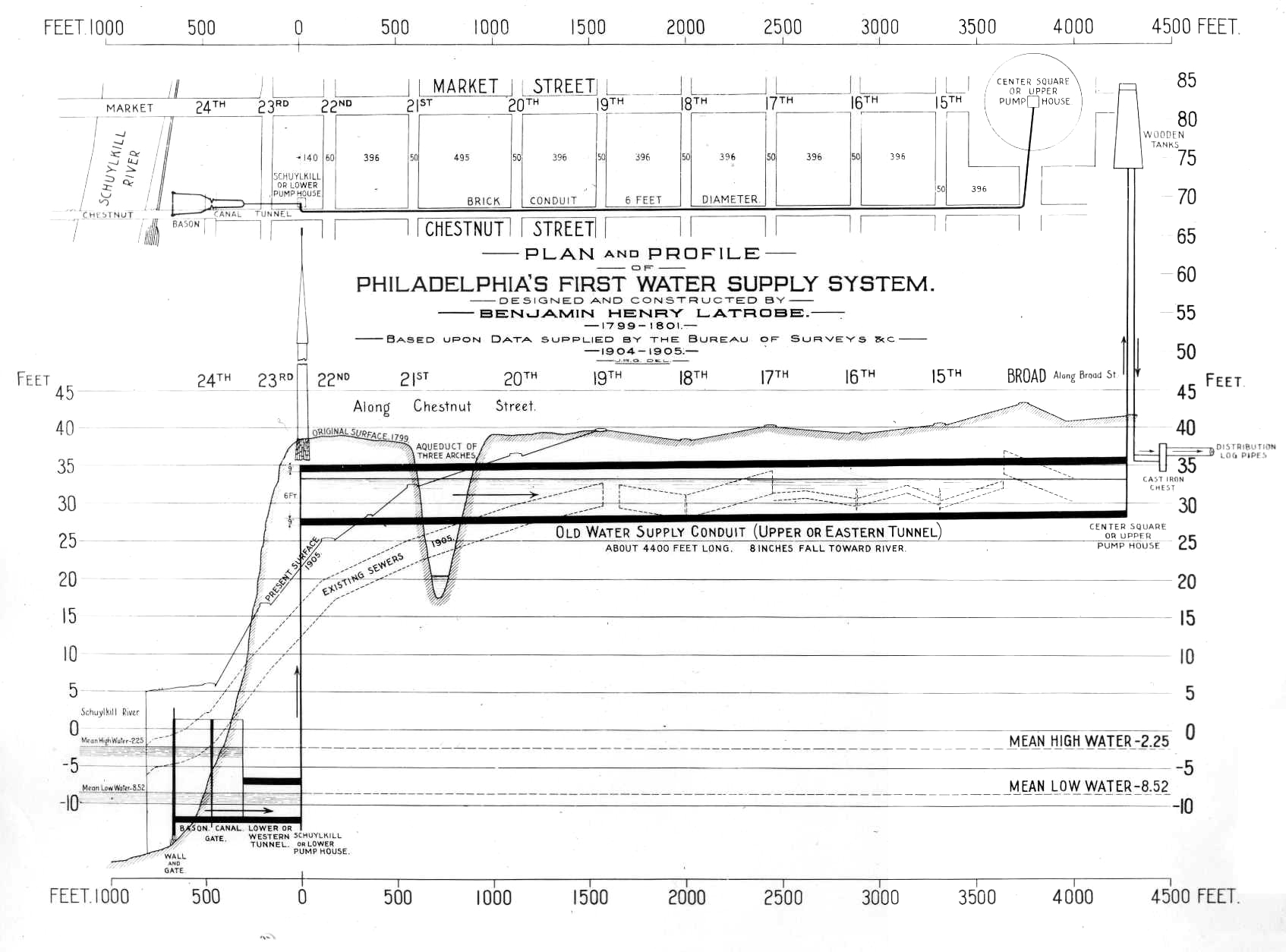
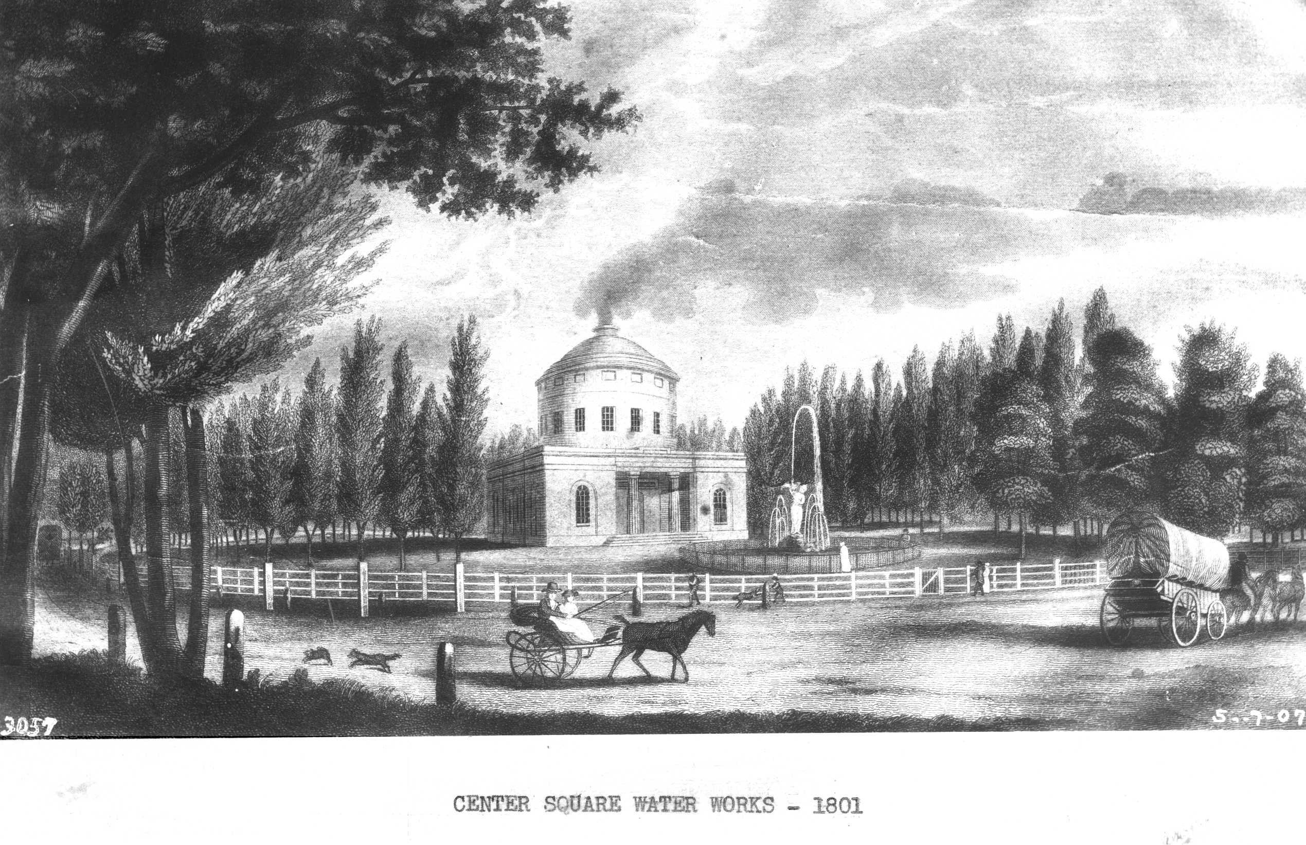
The site selected for the Centre Square Station or Upper Pump House was at the intersection of Broad and Market Streets, on the ground now occupied by the City Hall (1931). Keeping in mind that Latrobe was a successful architect as well as an eminent engineer, it is easy to understand why the building was beautifully designed, in harmony with the best architecture of the time. White marble was used for the exterior, and in its setting in the center of the public square or park surrounded by attractive shrubbery and trees, it had the appearance of a memorial edifice. This Centre Square, from which the station takes its name, was the gathering place of the people for public, municipal, social, and patriotic functions, and adorned by the building it became a place of beauty as well as one of usefulness. The building was 60 feet square to a height of 25 feet, which constituted the first story. This was surmounted by a circular upper structure 40 feet in diameter and 60 feet high topped by a dome. The first story contained the boiler, engine and pump rooms, a committee room, offices, and an engineer’s room. The upper structure accommodated the beam of the engine and the water tanks.
The engine and pump house at the Schuylkill end of Chestnut Street became known as the Schuylkill Engine House and was built according to a most substantial and solid design. This structure was 66 feet long and 54 feet wide, large enough to house two sets of engines and pumps, but only one set was ever installed.
The real problem was to find a contractor who could build a satisfactory steam engine that would fulfill the requirements. At this time (1799) there were only three known steam engines of any considerable size in the United States, one in New Jersey, one in New York, and one in Philadelphia. The steam engine in New Jersey was, as nearly as can be determined, of a lever beam type, constructed about the year 1763 by an Englishman, Josiah Hornblower, who imported the parts from England. This engine was located in the Schuyler Copper Mine on the Passaic River to keep the mine pits free of water which continually flooded the diggings and made the suspension of operations necessary. It is reported that this engine was quite successful, much to the satisfaction of the mine owner, Colonel John Schuyler. According to the biography of John Fitch, this English engine, erected at the Schuyler mines, was the third steam engine erected in the United States, the two others having been imported from England into New England about 40 years before the War of Independence. The engine of this time was built on the atmospheric principle of the Newcomen engine. The improvements of Watts had evidently not been accepted and employed.
The steam engine in New York was used in the sawmill of Nicholas J. Roosevelt, who was a native of the United States, born in New York City, December 27, 1767. His brother, James Jacobus Roosevelt, was a brother of the great-grandfather of Theodore Roosevelt who became the 26th President of the United States.
In Philadelphia the steam engine was used by Oliver Evans to grind plaster in his mill located at Ninth and Chestnut Streets. This engine was of the high pressure type, possibly one of the first of this type, with a cylinder of six-inch diameter and a stroke of 18 inches. The cost to build it was said to have been $3,700. The power developed could crush about 12 tons of plaster in 12 hours. Later this same engine was employed to drive 12 saws for sawing stone and accomplished this work at the rate of 100 feet of marble in 12 hours.
Previous to 1799 no municipality in America had employed steam as power for the operation of pumps to raise or propel water for public supply. Latrobe found it difficult to find an engine builder with sufficient skill and reliability to enter into a contract with the City of Philadelphia to build and maintain satisfactorily the steam engines for the Centre Square and the Schuylkill Pump House Works. Finally, Nicholas J. Roosevelt contracted at a total cost of $33,000 to build the two engines and the two pumps for the Philadelphia Water Supply system and bound himself to keep the engines in repair for five years. The specifications called for power and pump capacity to raise 3 million gallons of water to a height of 50 feet in 24 hours. When the engines were finished, in 1801, they were the largest steam engines in the United States.
The steam engine at the Schuyler Copper Mines in New Jersey gave Nicholas Roosevelt the ideas for a steam engine, which he built in New York, and his friendship with Latrobe, coupled with his success in reproducing a satisfactory engine, made him the individual best suited to undertake the water works equipment. The stipulation in the contract which called for keeping the water works engines and pumps in repair for five years proved exceedingly unprofitable and financially he became greatly embarrassed.
Difficulty was encountered in raising money by loans for the erection of the works, and several times the committee in charge was obliged to discount its joint individual notes in order to raise funds to carry on the work. The subscribers to the water loan were given a supply of water without tax for a period of three years from January 1801.
The Centre Square engine was a beam type and many wooden members entered into its construction, including the lever beam and driving shaft, as well as the balance or flywheel, cisterns, and the supporting and bracing members. The steam cylinder of the engine, 78 inches long and 36 inches in diameter, was cast in two pieces and united with copper. The joints were secured externally with a cast-iron band 18 inches wide. Nearly four months were occupied in boring it out and fitting it for use.
The pump was a double acting force type and had to be lined with sheet copper before it could be made airtight. Until 1810 it was operated without an air chamber. Then one was added but found to be useless until lined with sheet lead.
The Centre Square engine had a pump 18 inches in diameter with a 72-inch stroke. Its duty was 9 million pounds raised one foot high on consumption of one bushel of bituminous coal. Actually, it raised 962,520 gallons of water 50 feet to the tanks in 24 hours, consuming 55 bushels of coal. This figures but about 7.25 million foot-pounds to the bushel.
This engine pumped the water into two wooden tanks in the domed top of the building, 50 feet above the bottom of the brick tunnel which led from the Schuylkill engine house. One tank was 10 feet in diameter and 12 feet deep and the other was 14 feet in diameter and 12 feet deep, and together they held 20,855 gallons.
The water from the wooden tanks was conducted into a cast iron distributing chest, which diverted it into two bored log water mains, one of six inch inside diameter and the other of 4½ inch. The six inch main was laid in High Street (now known as Market Street) while the 4½ inch main was laid in Arch Street. In Chestnut Street there was laid another 4½ inch main. All three mains extended to Front Street. From them, three inch and 4½ inch bored log pipes distributed the water to the consumers.
The steam cylinder of the engine in the Schuylkill Engine House was 40 inches in diameter with a 72-inch stroke; the pump attached to it was 17½ inches in diameter, also built with a stroke of 72 inches. This engine ran 16 revolutions per minute, and in a test pumped 1,798,963 gallons of water in 24 hours, with a fuel consumption of 70 bushels of bituminous coal.
The first steam engines of the piston type did not make continuous use of the “pushing power” of steam. The top of the piston was always open to the atmosphere (hence the name “atmospheric engine”) while the bottom of the piston was alternately subjected to steam at about atmospheric pressure, thereby elevating the piston, and to a partial vacuum formed by the introduction of cool water directly into the to “lift off” the back pressure, thereby causing the piston to be depressed by atmospheric pressure. This engine might have been called a vacuum engine. About 1781 the double acting engine made its appearance. In this engine the steam under pressure was applied alternately at each end of the cylinder and exerted energy on each side of the piston. The Centre Square and Schuylkill engines were of this latter kind. They were what is commonly known as double acting, low pressure, condensing engines, their boilers operating on approximately 2½ pounds steam pressure.

FIGURE 7 is a drawing of the Centre Square engine and Engine House prepared by Frederick Graff, Jr., from the original drawings and memoranda in his possession. While the Schuylkill Engine House was of different construction (there were no tanks there) the pumping engine was essentially the same. The principal view is a vertical sectional elevation of the engine house, engine, and pump. I have applied legends and letters to the parts. (A) is the steam cylinder with the ordinary piston (B) and the piston rod (C) connected to the beam (D). (E) indicates the steam ports. The boiler (K) and steam cylinder (A) were connected by means of a steam pipe leading to the steam chest in which were located hand lever operated admission and exhaust valves, F-l and F-2.
The condenser (F) was an air-tight vessel of cylindrical shape immersed in cold water in a wooden cold water well (G). Steam discharged from the cylinder (A) into the condenser was liquefied by the action of the cold water. The water from the condenser (and any steam in the well which remained uncondensed) was drawn from the condenser by the air pump (H) which was arranged alongside and then discharged into the hot well (J) of the condenser, where the water was allowed to cool and afterward enter the cold well. The air pump received its motion by a rod connection to the beam (D). The air pump piston upon its upward stroke opened valve (8) and closed valves (6) and (7) forcing surplus water, air and a small portion of uncondensed steam through valve (5). Valves (5) and (8) were closed on the downward stroke of the piston, while valve (6) was opened and surplus from the condenser was discharged through valve (7).
Rocked about its pivot (l) by the rise and fall of the piston (B) and piston rod (C) connected to its one end, beam (D) operated the water pump and balance wheel (O) from its opposite end, connecting with piston rod (Q) and piston (S) by link (M) and with balance wheel (O) by link (N). When the pump was on its down stroke as illustrated by the positions of its valves in FIGURE 7, valves (1) and (4) were closed while valves (2) and (3) were open. The pump therefore took in water above its piston (S) and delivered the water below to the pipe (v). On the up stroke valves (2) and (3) were closed and valves (l) and (4) opened, and the pump then took in water below the piston and delivered to pipe (V) the water taken in above the Piston on the previous stroke. Air chamber (R) communicating with pipe (V) provided a cushion for the pulsations set up in the water by the pump’s reciprocation.
The boilers in both the Schuylkill and Centre Square Works were rectangular wooden chests, nine feet wide, nine feet high and 14 feet long inside, made of five-inch-thick white pine planks braced upon the sides, top and bottom with oak scantling 10 inches square, the whole securely bolted together with 1¼ inch diameter rods passing through the planks. Their detail construction is revealed by the cross sections of FIGURE 8.
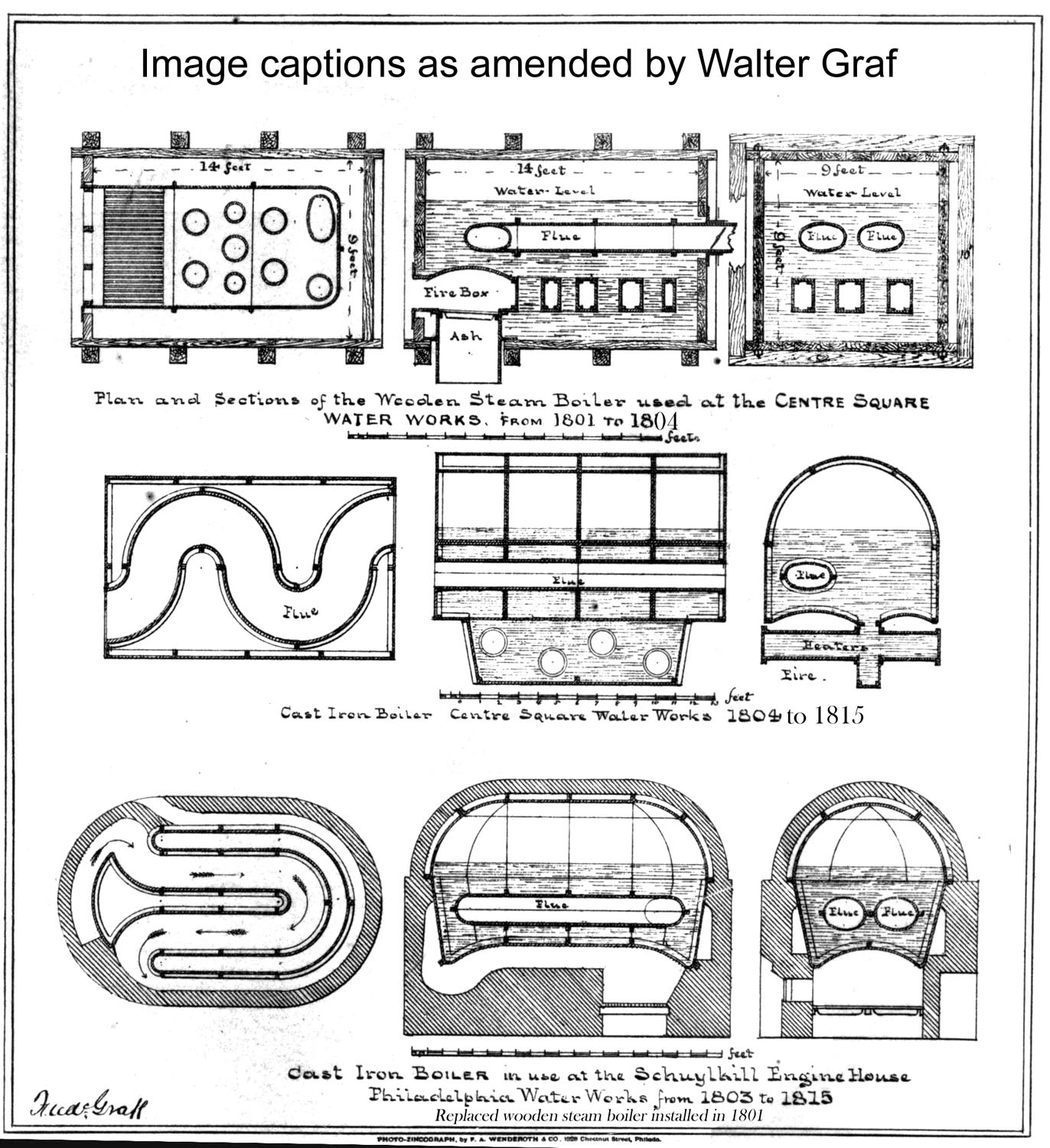
The fire box was placed inside the boiler and was made of wrought iron plates with vertical flues and horizontal connectors of cast iron. The fire box was 150 inches long, six feet wide and 22 inches deep. The vertical flues were eight in number, six of 15 inches diameter and two of 12 inches diameter. Through these flues the water circulated while the fire acted around them and passed up an oval flue located above the fire box and from the back of the boiler to near the front and then returned again to the back when it entered the chimney.
At this time no wrought iron could be obtained in sheets larger than 15 × 36 inches, when it was squared, and squaring had to be done by the purchaser. All of the imperfect castings were patched by gun borings, cement and hard solder. The wrought iron fire box and the cast-iron flues were not satisfactory on account of the leakage caused by the unequal contraction and expansion of the two different metals, so eventually wrought iron flues were put in.
The low heat conducting power of the wooden construction of these boilers was supposed to be of great advantage, but great difficulty was experienced in keeping them steam tight. Consequently, a new cast-iron boiler was constructed and installed in the Schuylkill works in 1803. It was so successful that a somewhat similar cast-iron boiler was installed in the Centre Square Works the following year. (See FIGURES 9 and 10).
The new boiler in the Schuylkill station had semi-circular ends, was 17 feet long and eight feet wide at the bottom, and 19 feet long and 10 feet wide at the top. The flame passed under the bottom and around the back into oval flues which passed through the boiler, returned, and passed around the sides outside the shell. Centre Square’s new boiler had a semi-circular top, the ends being flat, and the fire passed under the boiler and around heaters of irregular construction and through one flue of serpentine shape, to the front of the boiler just over the fire. These cast iron boilers remained in use until the steam water works at Fairmount were started on September 7, 1815.
According to the legend on the drawings prepared by Frederick Graff, Jr. (FIGURE 7) the Water Works commenced operation January 21, 1801. According to page 13 of the 1860 report of the Water Bureau by Mr. Henry P. M. Birkinbine, January 27, 1801, was the starting date.
The fuel consumption and its cost was very high. So great were the amounts of wood and bituminous coal used that fears were entertained that a shortage of supply and a price increase would result. Wood cost $4.50 a cord and coal $0.33 a bushel.
The Centre Square engine was able to fill its reservoirs in about 25 minutes, which just satisfied the demand at the time the Works began operation. If the pumps were not constantly at work the citizens suffered from lack of water. As the engines were defective in many respects because of inadequacy of tools and experience in building, and the boiler construction was poor, there were frequent shutdowns for minor or major repairs, and much annoyance and suffering was experienced from interruptions and shortages of the water supply.
Some of the major engine troubles are of interesting note. In 1805 the wooden lever beam of the Centre Square engine was found to be so badly decayed or worm-eaten that it had to be replaced. The wooden fly-wheel shafts of the engines also gave trouble, and they had to be replaced by shafts of cast-iron in 1809. An outstanding replacement was that of one of the engine piston rods, a rod four inches in diameter and 10 feet long. The forging and finishing of a new one in one of the city’s shops was considered quite a remarkable feat. The Watering Committee reporting it said, “Workmanship of this piece of iron could not in the opinion of the Committee have been better executed in any country.”
After wrestling with these difficulties for a period the City Councils had made a fresh survey of water sources, hoping to evolve a more adequate and efficient water works system. The subject was submitted to John Davis and Frederick Graff (who succeeded Davis as superintendent in 1805). These gentlemen made another examination of the Wissahickon and Spring Mill creeks and also the Schuylkill for some distance and presented an estimate of $359,718 for bringing the water of the Wissahickon creek into the city by means of pumping. The proposed plan was not followed.
Notwithstanding the many shortcomings of the Centre Square and Schuylkill stations, they were measurably successful and continued to give service for nearly 14 years, though at great cost to the city. The cost of these stations with yearly expenses, from March 1799 to September 1, 1815 (when a new steam operated water works was started at Fairmount) was $657,398.91, while the gross receipts amounted to but $105,429.68. Thus, the project fell short of paying for itself by $551,969.23.
It does not appear that any of the City’s engineers of this early period (Latrobe, Davis or Graff) realized the full potentialities of Franklin’s plan of damming up the Wissahickon and supplying the City by gravity through pipes, as did the Water Commission of Experts in 1875 (See Preface). Had such a plan been adopted, there would have been no such troubles as beset the operation of Latrobe’s steam pump system, the water supply would have been adequate to meet the demands of the growing city for many years, and possibly much money could have been saved in the long run. However, Philadelphia then could not have had her beautiful Wissahickon Park.