Chapter 4 of The Water Works of the City of Philadelphia: The Story of their Development and Engineering Specifications
Compiled in 1931 by Walter A. Graf (Staff Engineer, The Budd Company, Philadelphia), with the assistance of Sidney H. Vought and Clarence E. Robson. This online version was created from an original volume at the Historical Society of Pennsylvania, Catalog No. WZ 23591 (4th Fl. Folio).
Walter Graf History Home Page
(With Notes on the Text, Preface, and Acknowledgements)
Reading the Preface will give a quick overview of the beginnings and expansion of the Philadelphia water system.
IN 1802 THERE WAS BORN at St. Etienne (Loire) France a boy who was destined for fame, his name, Benoit Fourneyron. In 1827 when but 25 years of age he invented the turbine water wheel. In 1836 his beloved native country recognized this achievement by awarding him a prize of 6,000 francs. Of course there have been many improvements upon his original invention. Many exceedingly valuable improvements came from such Americans as Howe, Francis, and Morris, but all have been but refinements or betterments of Fourneyron’s original idea.
The water turbine, (‘turbine’ from the Latin word turbo, meaning a whipping top, spindle or reel) as invented by Fourneyron comprised a wheel (nowadays called a runner) revolving on a vertical shaft and having a peripheral series curved blades or vanes against all of which the water acts simultaneously as it rushes from all sides. The casing through which the water is delivered to the wheel is provided with guide blades, to give the water the direction best suited to attain efficiency. Water turbines are more efficient than breast wheels because they develop greater power from the same power flow. They are efficient at both the highest and the lowest falls of water.
Some years after Fourneyron achieved his invention another Frenchman, Jonval, developed, enlarged and improved designs of the Fourneyron turbine wheel, which he patented. Jonval, with Messrs. Koechlins and Company, had a young student in their employ named Emile Geyelin, whom they sent to the United States from France to exploit the Jonval Turbine patents in America. Geyelin undertook employment with the J. P. Morris Company of Philadelphia and this company secured the contract to build a Jonval turbine to augment the breast wheels in the Fairmount Water Works. Geyelin designed and engineered it. It was duly built and erected, and when placed in operation December 16, 1851 it became the ninth wheel of the Fairmount Station. (Refer to FIGURES 14 and 15 in Chapter 3, and Figure 16 below).
The addition of this first water turbine to the Fairmount Water Works was an accomplishment of Frederick Graff, Jr., who succeeded his father as head of the Water Bureau in 1847, and continued until 1856. Under his father’s direction Frederick Jr. had become a highly capable engineer, fully able to carry the responsibilities of the Water Bureau.
The runner of the Jonval turbine was none feet in outside diameter and provided with blades one-quarter inch thick, 13 inches wide and 10 inches deep, and its vertical shaft was nine inches in diameter. The guide casing was over 10 feet in outside diameter. Its guides were one-half-inch thick. Motion was communicated to the crankshaft of the pump through a pair of bevel and a pair of spur gears. The pump was of 16 inches diameter and 72 inches stroke and of the same construction as the pumps driven by the breast wheels. Its rated speed was about 12 double strokes per minute, and its capacity at that speed 87,408 gallons per hour or 2,097,792 gallons per day.
The space available in the Fairmount steam pumping station building was rather cramped and the new turbine was large. As a result the completion of its installation was considerably retarded because of the difficult and tedious methods that had to be employed in order to get the large castings into their proper positions. However, installation was finally completed and when tested both wheel and pump gave evidence of giving complete satisfaction.
The success of this wheel was considered very important, inasmuch as it indicated that further turbine wheel installations would probably so considerably increase the efficiency of the Fairmount water powered works as to render it unnecessary to resort to steam power for increased capacity. Steam power had been found to be more expensive than water power. It was computed that if turbine wheels were substituted for all the breast wheels to drive the existing pumps enough additional power could be had to raise an additional 4,166,281 gallons per day to the reservoir; and if the pumps then in use were replaced by larger ones, the additional gallonage would amount to 6 million gallons per day. The water from the pump reached the reservoir through the old main (433 feet long) which had been provided for the original driven pumps.
This first water turbine worked under a head and fall of six feet six inches at high tide, and 10 feet at low tide. An outstanding advantage over the breast wheel was that it could run constantly for 24 hours a day as the rise and fall of the tide has no effect on it.
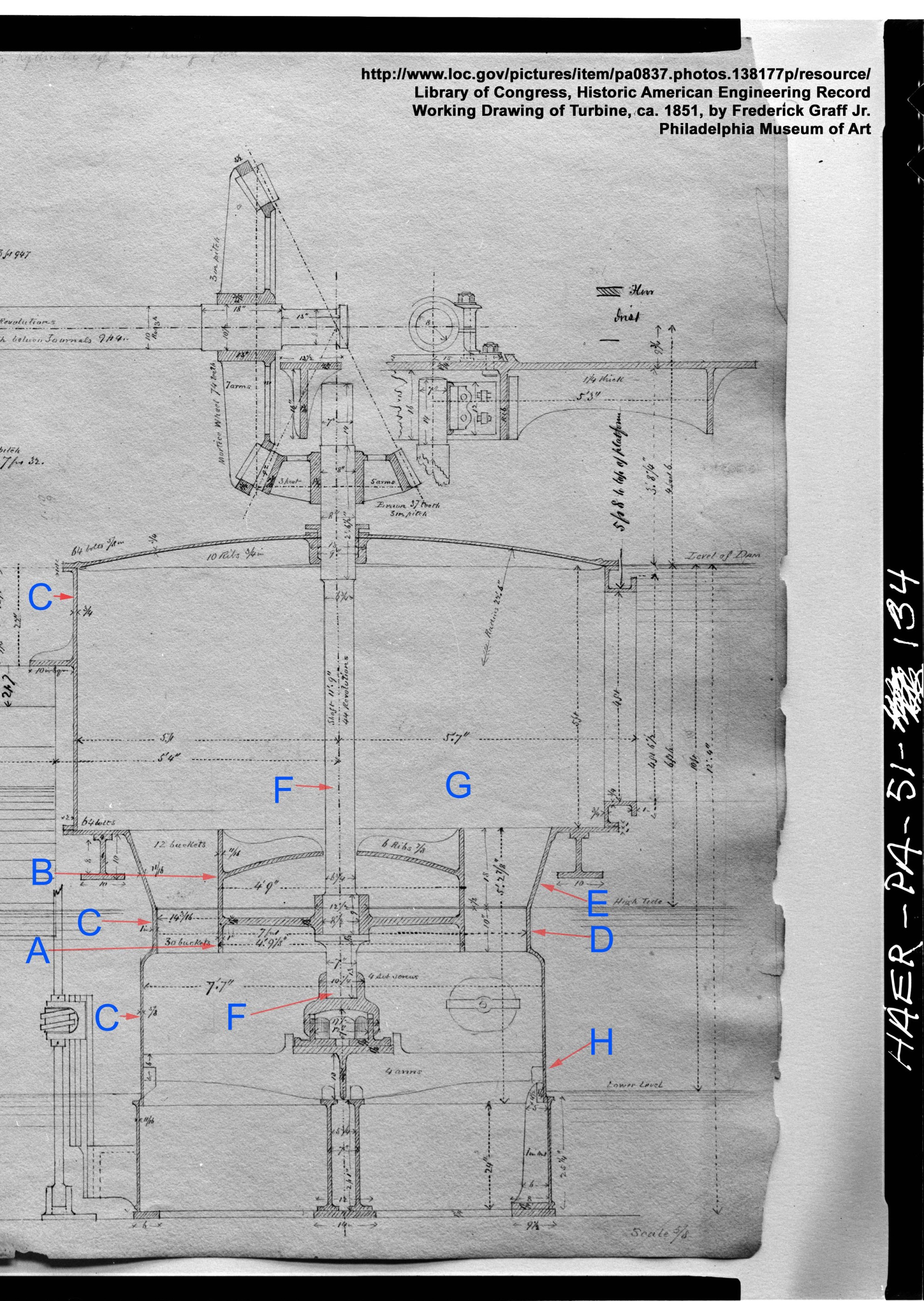
Some idea of the details of construction of the Jonval Turbine may be had by reference to FIGURE 16, which presents a vertical section of the Geyelin design. The portion marked A is the so-called wheel or runner, B is the so-called fixed wheel or guide casing, and C the casing at large in which they are located. The 50 so-called blades or vanes D of the runner were equally spaced around its periphery and were bound around their outer edges by a wrought iron band.
The runner was keyed to the shaft F, and was turned off true on its upper face and outer edge and fitted to run freely under the guide casing and within the cylindrical lower part of main casing C. The guides or vanes E formed 17 chutes equally spaced around the periphery of the guide casing which latter in turn fitted closely against the conical sides of the upper part of main casing C. The wheel shaft F passed inwardly through the top plate of the fixed wheel and out through a bearing at the top of casing C.
The conical part of the main casing C in which the fixed wheel or guide casing rested, and the cylindrical part in which the movable wheel or runner turned, were finished by boring, and the under edge of the guide casing B, where it meets the rim of the runner, was faced off so that the runner could revolve nearly in contact with it.
Water from the flume entered the chamber G above the fixed wheel B, and passed into the chutes formed by the guides E and acted upon the blades D of the movable wheel. Guides E and blades D were curved to correct shapes and were oppositely inclined at such angles as to afford the most effective impact and pressure of the falling water on the runner B.
After the water had performed its work in the wheel, it escaped downwards through a draft tube which was a continuation of the casing C. This draft tube H was enlarged immediately below the wheel to give the escaping water an unobstructed flow, and its end was submerged in the tail water to make a draft column of the escaping water and so increase the power. The runner of the Jonval turbine, in common with all such wheels where the draft tube is used, occupied a position intermediate the head water and the tail water. When the water is shut off at the head the wheel is freed of water and is in a convenient position for examination and repair. The guide casing B was not permanently fastened in the main casing C and so could be raised for removing obstructions or for repair. This feature in turn also permitted the runner A to be raised, whenever the step bearing or any of its parts needed repairing, thereby obviating the necessity of taking apart the main casing C. The main casing, gate, base plate, and wheel centers were made of cast iron. The shaft was of wrought iron.